
Author:
(1) Lothar Moeller, SubCom, Eatontown, NJ 07724, USA, [email protected].
Table of Links
GPS Long-Term Stabilized RF Phase Meter
Simple and Accurate models for tides
Latency Variations on Transpacific Cable
Poisson effect on pressurized cables
Conclusions, Acknowledgments, and References
2. GPS LONG-TERM STABILIZED RF PHASE METER
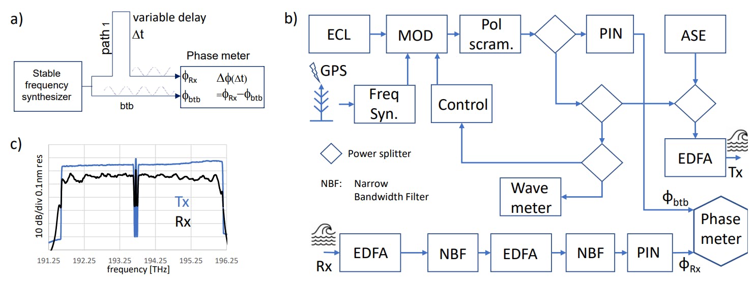
The key idea behind our experiment is to assess path length changes by measuring the phase delay of an RF signal that propagates on an optical carrier through the cable. An ultra-stable phase meter compares the arrival phase of an RF signal at the cable output with a stable local reference (btb) as sketched in Fig.1a.
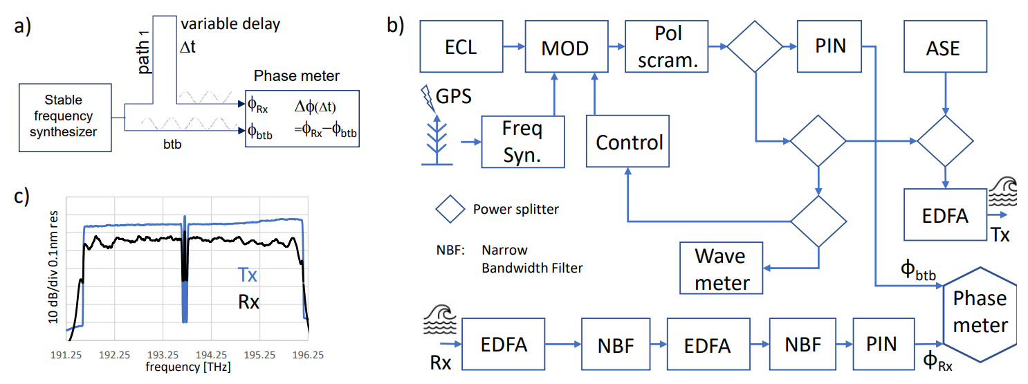
Any delay variation in path 1 would be captured as a varying phase difference. Contrariwise, a varying phase difference does not automatically point to a length fluctuation; but could also originate from a frequency drift in the RF signal. Typically, signal propagations last over ~100 ms and recordings run weeks. Therefore, a correspondingly stable frequency synthesizer is essential in these experiments. Our Rubidium-controlled OCXO synthesizer locks to a 10-MHz standard, derived from a GPS signal and ensures excellent short-, medium-, and long-term stability. The synthesizer drives an optical LiNbO3 (Fig.1b) modulator connected via a PM fiber to a cw external cavity laser (ECL). A weak optical feedback keeps it locked to the null of its characteristic curve. The modulator driven at 10 MHz imprints a 20 MHz RF tone on the carrier (~10 m RF-wavelength). Chromatic dispersion converts any wavelength drift of the carrier into latency variations of the received signal, i.e. creating an artifact. Tapped signals fed into a wavemeter and an O/E converter enable us to study the impact of the remaining ECL’s - drift in measurements and serve as btb signal for the phase meter, respectively. The probe combined with a 100 GHz wide ASE gap spectrum enters the wet plant at ~ -5 dBm (Fig.1c). The ASE loading carries most of the repeater output power to ensure linear propagation of the probe, which then gets optically looped back at the other end of the cable and is received using an amplifier/ filter cascade, followed by a PIN receiver. Our commercially available phase meter samples the received probe and the btb signal at about 30 S/s. Its intrinsic noise is negligibly small. A fast polarization scrambler mitigates link PDL and PMD impacts. We assume that an optical path length change equals twice the cable length change.
This paper is available on arxiv under CC BY 4.0 DEED license.